welcome to mies and peas!
Monday, September 19, 2011
MIES - Angled Library
This is a private library which showcases detailed woodwork with peculiar jointed connections. The bookshelves are a marvelous way of emphasizing the perpetually braced frame that this architect, Gianni Botsford, employs for his lateral structural device (I've been talking about this a lot, haven't I?).
By coupling indigenous methods and materials with modern technologies, Botsford has created a pavilion-like studio setting for a writer in Costa Rica with this design. The finished product is both livable and highly functional, and it's stilted presence off the ground allows for the passage of winds to circulate over and underneath, while cooling the underside of the entire structure simultaneously.
The wood is sourced from local timber, and sits on similarly sized wooden stilts (each of which transfers into a small concrete pad foundation at the base joints). Roof beams up to 10 m long and .355 m deep allow for an interior with no vertical columns, which frees up the circulation space inside.
The pitch of the roof is singular and continuous, and elevates toward the sea shore to block out excessive gusts. The interior is completely louvered as well, to mitigate wind effects caused by lighter components and cladding in the enclosure (as in glass).
Set a short distance along a raised walkway, a second smaller pavilion mirrors the first. This contains sleeping quarters and a bathroom. The cladding is the same (as in the corrugated steel building) and continues to use local construction materials. The overall finished product is both elegant, somewhat foreign and yet very familiar.
Sunday, September 18, 2011
BDCS - I-Joist
(From Wikipedia) An I-Joist (or an engineered wood joist) is a product designed to reduce many of the problems that occur with using conventional wood joists. It is a manmade engineered wood product which has incredible strength and durability in relation to its size and weight. The biggest notable difference, other than their look, compared to dimensional lumber is that the I-joist is designed to carry heavy loads over long distances while using less lumber than a dimensional solid wood joist of a size necessary to do the same task. Approximately 50% of all wood light framed floors in the United States are framed using I-joists.
An I-joist comprises two main parts, the web and flange. The web is sandwiched between a top and bottom flange, creating the “I” shape. The flange can be made from laminated veneer lumber or solid wood finger-jointed together for ultimate strength. It is then grooved on one side to receive the web. The web is typically made from plywood, laminated veneer lumber, or oriented strand board. After cutting the webs and flanges to the specified widths and lengths, they are assembled with water-resistant glue by pressing the web into the top and bottom flange. After initial assembly, the I-joist is then end-trimmed and allowed to cure in an oven, or at room temperature to approximately equilibrium moisture content. The sizes manufactured vary on the I-joists intended load and span. Their depths can range from 9 ¼ inches to 24 inches (145mm - 600mm) and are available up to 80 feet long, although 12-13m is more common. The intended use for an I-joist is for floor joists, wall studs and roof rafters in both residential and commercial construction.
I-joists will not bow, crown, twist, cup, check, or split as would a dimensional piece of lumber. Also, I-joists are designed to help eliminate squeaky floors by being more dimensionally sound and featuring little to no shrinking. Although the I-joist may seem like a perfect choice as a building material, if it is installed incorrectly or altered the I-joist can fail. By reading the manufacturer’s instructions with the I-joist, most mistakes can be caught in advance. The most common mistake typically is with subcontractors misplacing or improperly sizing holes in the web. Doing so can greatly compromise the strength of the joist and the ones around it potentially leading to structural failure in those joists. Some of common mistakes made with installing I-joists are: cutting or chiseling flange in any way, improperly sized joists hangers, improper nailing into rim joist and joist hangers, and wrong sized nails. Another situation to look out for is matching the rim joist depth to the I-joist size. Improper matching can lead to too much strain on the I-joist. To solve the problem the rim joist can be made from rips of ¾ inch plywood, or engineered rim joist matching the I-joist in depth. A similar situation occurs where the I-joist crosses a main beam. Installing squash blocks (2x4 materials 1/16 inch higher than the I-joist) alongside the I-joists helps take the load of the above levels off the I-joist themselves and onto the main beam. Problems that arise while installing the sheathing are missed nails and having the glue set too fast. Both can lead to an uneven or squeaky floor.
Below is an example of how I-joists are typically framed into floors (which they are used mostly for). I-joists can also be used for walls and lateral bracing systems.
Friday, September 16, 2011
BDCS - Brise Soleil
In the typical form, a horizontal projection extends from the sunside facade of a building. This is most commonly used to prevent facades with a large amount of glass from overheating during the summer. Often louvers are incorporated into the shade to prevent the high-angle summer sun falling on the facade, but also to allow the low-angle winter sun to provide some passive solar heating.
On the Arab World Institute, where Nouvel pioneered his brise soleil innovation in his Institut du Monde Arabe: one sees a glass-clad storefront where a metallic screen unfolds with moving geometric motifs. The motifs are actually 240 motor-controlled apertures, which open and close every hour. They act as brise soleil to control the light entering the building. The mechanism creates interior spaces with filtered light — an effect often used in Islamic architecture with its climate-oriented strategies. This building catapulted Nouvel to fame and is one of the cultural reference points of Paris.
Sunday, September 11, 2011
MIES - Nest
What if you brought the world into your home with you? This small home, located at the foot of a mountain near Onomichi City, Japan, was built by UID architects for a family of four. In the family, there were three females (one mother and two daughters) and an early concept of the house included a sense of nesting, which echoed their sentiments as to the home they would like to live in. The eventual design expanded this idea a little, transforming the nest into a forest within. A from that, standard Japanese philosophies of transcendence, from forest to earth to universe, overrode, giving this final home a sense of scale.
The entrance to the home is one the ground floor. Visitors pass through a planted garden (shown above) the grows up to the full height of the house. This is in standard line with Japanese mythology, where trees such as peach blossoms represent powerful universal ideals.
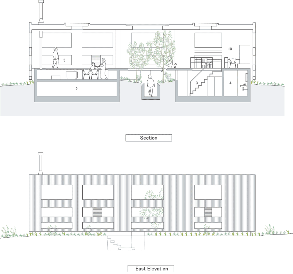
The whole building feels like a single space. As a structure, it comprehends surroundings and environment by rethinking elements such as floors and walls. In the ground layer, some spaces are connected to each other by a tunnel that becomes concrete, which gives a sense of foundation.
Above the ground, a floating wooden nest box composed of branches and fallen leaves cover the nest on the ground surface. Although the composition floors, voids and walls make the architectural elements seem separated, they instead become vital links of architecture to the outer context, and help one from inside view the world beyond.
And from the plans and elevations, we see this continue. The apertures are placed evenly near the living quarters of the home and increase in height (rather than decrease) as the elevation rises. This stays true to the sense of universal scale, and falls away from conventional architectural thinking. It is emblematic of the best in natural Japanese philosophy and as such, somewhat transcends its own architecture entirely.
Thursday, September 8, 2011
MIES - LA Design Center
This project is from John Friedman and Alice Kimm Architects in Los Angeles, California. It is a design that transforms two derelict warehouses in South Los Angeles into a communal design center which is mainly a venue for cultural events. The project has 20,000 sf of exterior event space and 80,000 sf of convertible interior/exterior space. Because the project is yet to be expanded (there are four phases total), having adaptible space was crucial to the initial design.
Friedman and Kimm respect historical and local materials of Southern California. The brick and stone construction suggest a permanence, but the quantity of daylighting conversely suggests the opposite. According to the architects, the building is designed to "hide, reveal and filter" aspects of the original construction, and to an extent, that is precisely what it does.
Some irregular materials were used here: polycarbonate, cement board, fabric, zinc-coated sheet metal (galvanized) and typical lumber. The main reasons why these materials were chosen were contextual (they are available in L.A.) and also because they were affordable and easy to use. Their inherent simplicity also adds to the rustic suburban aura.
The main exterior space between the two buildings serves as asocial center of the project and can be used as an ordinary parking lot or a large event space. Several large parties, including the 2005 Los Angeles Chapter AIA Gala, have encouraged many Angelenos to visit this neighborhood they have never been to before.
The contractors sandblasted the walls to bring warmth to the existing wood and masonry construction. In the lobby, two bays of the second floor were removed and a stair was added to bring visitors up into the showroom space. Exposed bridging and long span wood construction was emphasized inside to give the space a nuance of openness and accessibility.
Tuesday, December 15, 2009
BDCS Notes - Wood

Pros of Using Wood:
1. Available
2. Low Cost
3. Ease of Use
4. Durability
5. Good for Use in Compression
Used extensively for buildings, bridges, utility poles, floors, roofs, trusses, and piles.
Engineered Wood Products: Laminates, plywood, and strand board.
Trees: A woody plant that attains a height of at least 20 ft., has a self-supporting trunk with no branches for about 4 ft. Over 600 species of trees in the United States.
Trees are classified as either endogenous or exogenous, based on type of growth. Endogenous trees, such as bamboo, grow with intertwined fibers. Wood from endogenous trees not used for engineering applications. Exogenous trees grow from the center out by adding concentric layers of wood around the central core. Structural applications for wood primarily concern the use of exogenous trees.
Exogenous trees are classified as either deciduous or conifers, producing hardwoods and softwoods, respectively.
Softwoods are softer, less dense, and easier to cut than hardwoods (although Balsa is a hardwood). They are also used more in construction than hardwoods. Hardwoods are typically used for furniture and decorative veneers (because of their nice grain pattern).
Deciduous trees shed their leaves at the end of each growing season. There are about 40 different kinds of deciduous trees used for commercial hardwood production.
Conifers (evergreens) have needlelike leaves and normally do not shed at the end of the growing season. They grow continuously through the crown to produce a uniform stem and homogenous characteristics. Softwood comes from 20 different kinds of conifers. The softwood is primarily used for structural purposes. The rapid maturing of conifers makes them a renewable resource.
Thursday, May 28, 2009
PPP Notes - Retaining Walls

SITE DEVELOPMENT
RETAINING WALLS
- Retaining walls are designed and constructed to resist the thrust of the soil, which can cause the wall to fail by overturning, sliding or setting.
- In stone walls, resistance to soil thrust can be helped by battering the stonework (i.e. recessing or sloping the masonry back in successive courses).
- Garden-type retaining walls, usually no higher than 4 ft., are generally made from small building units of stone, masonry, or wood.
- For higher walls, reinforced concrete is more commonly used.
- Terracing may be built with walls of wood, stone, brick, or concrete.
- Walls less than 2 ft. high do not require drains or weepholes.
- Preservative-treated wood is recommended for any design in which wood comes in contact with the ground.
- Redwood may be substituted if desired.
- Stagger vertical joints from course to course 6 in. minimum horizontally. The thickness of the wall at any point should not be less than half the distance from that point to the top of the wall.
CAST-IN-PLACE CONCRETE RETAINING WALLS
- When designing cast-in-place concrete retaining walls, keep these guidelines in mind:
- Provide control and/or construction joints in concrete retaining walls approximately every 25 ft. Every fourth control and/or construction joint should be an expansion joint. Coated dowels should be used if average wall height on either side of a joint is different.
- Consult with a structural engineer for final design of all concrete retaining walls.
- Concrete keys may be required below retaining wall footing to prevent sliding in high walls and those built on moist clay.
Sunday, May 17, 2009
PPP Notes - Basement Walls

BASEMENT CONSTRUCTION
(These notes are compiled from AGS)
BASEMENT WALL CONSTRUCTION
- Basement walls may be constructed of various materials, including concrete, masonry and wood.
CONCRETE BASEMENT WALLS
- Concrete basement walls may be either cast-in-place or precast.
- Cast-in-place concrete basement walls provide a cost-effective means of supporting a floor and resisting soil pressures.
- Commercial and residential applications of cast-in-place concrete basement walls are prevalent.
- Forms are easily placed in the excavation on the footings
- Reinforcing steel may be tied on or off-site, and is placed within the wall formwork.
- Depending on the soil and groundwater conditions, dampproofing should typically be used on foundation walls and waterproofing is generally required on basement walls prior to backfilling.
- Unless lateral bracing is utilized, the top of the basement wall must be supported by the first floor and the base of the wall by the footing or slab-on-grade before backfilling against the wall can begin.
- Keeping the wall heights uniform, as well as reducing the number of penetrations and maintaining a simple plan configuration, will help reduce the final cost of the wall.
- Precast concrete basement walls enable basement walls enable construction in less time than conventional cast-in-place concrete.
- In addition to the time and construction methods other advantages of precast concrete include the ability the ability of the precast supplier to utilize concrete admixtures that focus on ultimate strength, rather than cure time and temperature.
- Precast concrete manufacturers are able to produce mixes that cure to 5000 psi, which is stronger than concrete unit masonry or cast-in-place concrete walls.
- Additionally, better control of the concrete mixture and curing environment allows the use of low water/cement ratios, which results in a dense material that reduces water penetration.
MASONRY BASEMENT WALLS
- Masonry walls have long served as foundations for structures.
- Today, most masonry basement walls consist of a single wythe, or hollow, solid concrete masonry units, depending on the required bearing capacity.
- The walls are reinforced as necessary to resist lateral loads.
- Generally, such reinforcing should be held as close to the interior face shell as possible, to provide the maximum tensile strength.
- Basement walls should protect against heat and cold, insect infestation (particularly termites), fire, and penetration of water and soil gases.
- If radon is a major concern, the top course of the masonry and the course of masonry at or below the slab should be constructed of solid units or fully grouted hollow units using foundation drain to collect and drain condensation moisture from basements, should be avoided in areas where soil-gas entry is a concern.
- Architectural masonry units may be used to improve the appearance of the wall.
- Masonry units with architectural finishes facing the interior can be used for economical construction of finished basement space.
- Masonry easily accommodates any floor plan, and returns and corners increase the structural performance of the wall for lateral load resistance.
TREATED WOOD BASEMENT WALLS
- The construction of treated wood foundations and basement is similar to the construction of standard wood light-frame walls except for two factors:
- The wood used is pressure-treated with wood preservatives.
- The extra loading and stress requirements caused by below-grade conditions must be accommodated in the design and detailing of the fasteners, connections, blocking, and wall corners.
- As with standard masonry or concrete foundations, treated wood foundations require good drainage to maintain dry basements and crawl spaces.
- However, the drainage system typically used with treated wood foundations is different from that used with masonry or concrete systems.
- The components of a drainage system suitable for use with treated wood foundation include:
- A highly porous backfill material, which directs water down to a granular drainage layer.
- A porous granular drainage layer under the entire foundation and floor to collect and discharge water.
- Positive drainage of water by means of a sump designed for the soil type. This drainage system (developed for treated wood foundations) takes the place of a typical porous backfill over a perimeter drainage pipe.
- Benefits of a treated wood foundation include system:
- All framing is standard 2 by construction.
- Treated wood foundations can be erected in any weather and when site access for other methods is difficult.
- Deep wall cavities allow use of high R-value thermal insulation without loss of interior space.
- Wiring and finishing are easily achieved.
- Considerations when working with treated wood foundations:
- Treated wood foundations are not appropriate for all sites. Selection of the proper foundation for a project depends on site conditions, including soil types, drainage conditions, groundwater, and other factors. Wet sites in low areas (especially areas with coarse-grained soil) should be avoided if a full basement is desired, although a crawl space type foundation can be used in these cases. Consult a geotechnical engineer to determine the viability of any foundation system. Also, refer to the wood deterioration zones in all fifty states. Lumber and plywood used in treated wood foundations must be grade-stamped for foundation use. These are typically pressure treated with chromated copper arsenate. Treated wood products used in foundation construction are required to contain more preservatives than treated wood used in applications such as fencing and decking. Codes generally call for hot-dipped, galvanized fasteners above grade and stainless steel fasteners below grade.
- Avoid skin contact and prolonged or frequent inhalation of sawdust when handling or working with any pressure-treated wood product.
- Consult applicable building codes and the American Forest Paper Association’s Permanent Wood Foundation System – Design, Fabrication, Installation Manual for requirements and design guidelines.
- In the early stages of a project, consult with the building code officials for the area or jurisdiction to assess their familiarity with and willingness to approve this type of construction.
- The vertical and horizontal edge-to-edge joints of all plywood panels used in these systems should be sealed with a suitable sealant.
- Correct materials and details of construction are very important for treated wood foundations. If the contractor to be used for the installation is unfamiliar with this foundation type. The design should include the use of shop-fabricated foundation panels. Most problems with treated wood foundations can be traced to improper installation by inexperienced workers.
- This type of foundation depends especially on the first-floor deck to absorb and distribute any backfill loads; therefore, backfilling cannot occur until the first floor deck is complete unless lateral bracing is provided.