 Finite element analysis is useful, even essential, for achieving optimum results with new composite materials (carbon, Kevlar). Of course, the method can also be used for work with metals (steel, aluminum, titanium). But how does it work? Well, the essence of FEA is to break a large stress analysis problem into many smaller ones, which are then collectively solved by computer. This calculus-like appeal of finite element analysis method is one reason it has become a proven tool of structural engineering.
A very basic example of where finite element analysis might be used is the fabrication of a bike frame, which needs to be stiff enough, strong enough and also light enough to withstand the live load of a person while being aerodynamic and slender in form for optimum velocity.
The Trek 2000, a bike manufactured at the beginning of the last decade, was one of the first to utilize this kind of structural engineering. The following is the design stages they implemented to fabricate the bike form (from sheldonbrown.com, a respected biking site):
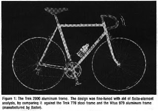
"1) Construct a complete finite-elements model for the new frame design, as well as for two popular high performance frames: a Trek 770 (Reynolds 531C steel) and a Vitus 979 aluminum frame (manufactured by Bador of France), all of equal size (60 cm). The Trek 770 and the Bador frames are the "base cases" against which the new design was compared.
2) Apply a variety of loading conditions to all frames to calculate their response characteristics.
3) Identify which loading conditions are critical in the design, in terms of undesirable responses (high stresses, high deflections, etc.). Establish which loads may be safely ignored.
4) Look for relationships between strength, stiffness, and weight by studying (graphing, plotting, etc.) the output data from the previous steps. Seek intuitive insights from the data about each frame's structural character.
5) Recommend future designs, and apply the various critical load cases to gauge their performance."
Elements of Finite Element Analysis (essentially, the mechanics of materials values):
1. Thickness
2. Coefficient of Thermal Expansion
3. Density
4. Young's Modulus of Elasticity
5. Shear Modulus
6. Poisson's Ratio (ratio of transverse to axial strain)
Element Properties
1. Straight/curved one-dimensional elements exhibiting axial, bending and torsional stiffnesses are suitable for cables, braces, trusses, beams, stiffeners, grids and frames. Straight elements have two nodes (for two ends) whereas curved elements have three. Elements are always placed at the centroidal axis of actual members.
2. Two-dimensional elements for membrane action (planes) and bending action (plates, shells). Curvature of basic shapes (triangles, quadrilaterals) included. Nodes typically placed at corners, sometimes at edges, seldom inside the element (but it can happen). The placement of additional nodes increases accuracy in the determining what an element may or may not do.
3. Torus-shaped elements are used for elements involving multiple symmetries. This can include plates, shells (one-dimensional) and solids (two-dimensional). Essentially, the torus-shaped elements involve the multiples of the first two elements in various assortments.
4. Three-dimensional elements for modeling 3-D solids such as machine components, dams, embankments or other masses. Common elements include tetrahedrals and hexahedrals in structural analysis. Nodes are placed at the vertices and possibly in the element faces or inside the element.
Element Interaction
Elements are only connected at exterior nodes and cover the interlocked domains very accurately (in an ideal structural analysis). Nodes have displacements or degrees of freedom which include translations, rotations, and higher order derivatives of displacements (if necessary). The displacement of nodes causes the dragging of structural members, which helps approximate the nature of a structural solution or remedy should the building fail.
Most of the math for element interaction involves linear algebra, and for that, this blog respectfully declines at moment to delve into that rabbit hole (although we will get there in time, we promise!). Another method of design for structural members, which has gained steam thanks to the evolution of computers, is the direct stiffness method. And that is our next topic of concern.

No comments:
Post a Comment